-

ส่งอีเมลถึงเรา
sale@lscmagnetics.com -

เบอร์ติดต่อ
+86 -13559234186
ส่งอีเมลถึงเรา
sale@lscmagnetics.comเบอร์ติดต่อ
+86 -13559234186

Magnetic formwork is rapidly gaining popularity in precast concrete production, yet the quality of on-site installation varies widely. Even the strongest magnetic box cannot compensate for air-gap losses caused by residue on the casting bed, and even the fastest formwork setup will not prevent side formwork from shifting during pouring and vibration. Drawing on actual precast production practice, this article outlines the key steps of magnetic formwork installation—from bed cleaning to stripping and reuse—and highlights the easily skipped steps that directly determine dimensional accuracy.
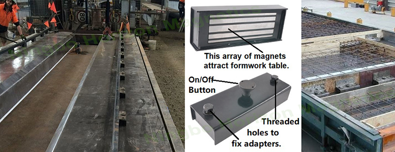
The holding force of magnetic formwork depends on tight contact between the underside of the magnetic box and the steel casting bed. Concrete debris, rust, or oil left on the bed creates air gaps that significantly weaken the magnetic circuit. Key points: Scrape the bed clean of all residue; wipe oily areas with solvent and dry with a clean cloth; check the underside of each magnetic box for adhering iron filings and remove them immediately. Otherwise, the box is effectively sitting on a spacer, which sharply reduces its holding force.
Before placing the side formwork, mark the setting-out lines on the bed to the dimensions shown on the drawing. Magnetic box spacing must follow the layout drawing: adjacent clamping points should generally be no more than 1 m apart, with closer spacing at ends and corners. A common problem on site is placing the boxes haphazardly and spacing them by eye, which causes the middle of the side formwork to bulge outward during pouring and vibration. The correct sequence is to align the side formwork to the setting-out lines first, then mark the box positions, making sure each box bears on the pressure flange of the side formwork rather than merely resting on its edge.
Once a magnetic box is in position, press the knob or throw the handle to engage it. The key action here is not "pressing down" but "confirming it is fully engaged"—some boxes have long-travel buttons, and operators wearing gloves can easily misjudge this. After fixing, check the length, width, and diagonals of the side formwork enclosure with a tape measure. Checking the diagonals is especially important for rectangular components, since measuring length and width alone will not reveal skew. If a deviation is found, tap the side formwork gently with a rubber mallet to adjust it; never pry the side formwork while the magnetic box is still engaged, as this can damage the box housing or scratch the bed.
Apply the release agent after the formwork is set up, not immediately after cleaning the bed, to avoid oil contamination when the magnetic boxes are engaged. Coat the inner face of the side formwork evenly, with no misses or puddling. For embedded parts (junction boxes, sleeves, diagonal-brace inserts, etc.), fix them first with magnetic bases, then tie them to the reinforcement cage as a secondary measure. Note that magnetic bases have limited shear resistance under vibration; larger embedded parts should be secured by tying or with fixtures, and magnetic holding force alone should not be relied on.
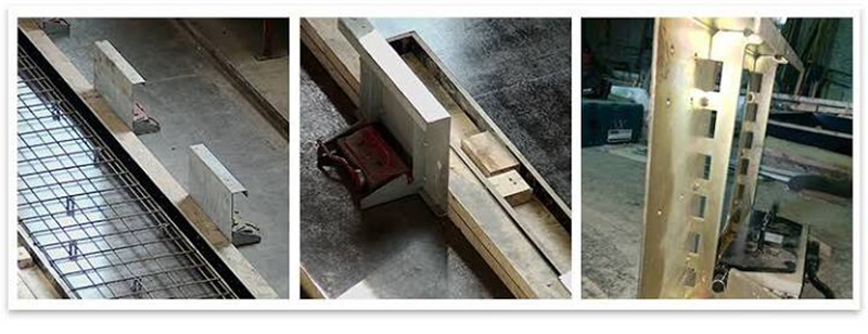
Pouring and vibration are the most critical stage for magnetic formwork. If the vibrator touches the side formwork or a magnetic box directly, the instantaneous shear force can exceed the box's slip resistance and displace the side formwork. Requirements: keep the vibrator at least 100 mm from the side formwork and never insert it directly over a magnetic box; avoid heaping concrete against one side of the formwork—pour symmetrically on both sides. If visible displacement occurs during vibration, stop vibrating that area immediately and reset the formwork before initial set; once the concrete begins to harden, it will be too late to adjust.
Stripping requires the concrete to have reached the specified strength (usually at least 50% of design strength, depending on component type and applicable standards). Release the magnetic boxes first: turn the knob or pry the release lever, confirm the magnet is fully disengaged, and only then remove the boxes and side formwork. A common mistake is to strike the side formwork with a hammer before the box is fully released and force it off, which either damages the casting bed or deforms the formwork. For components with window openings or irregular side formwork, strip in the order of "end formwork first, then side formwork" so that the last panel is not gripped too tightly by the concrete.
Before reuse, check each removed magnetic box for housing deformation, smooth knob/handle travel, and dents or burrs on the underside. A deformed box may still hold, but its actual contact area is reduced and its holding force drops noticeably. After each turnover cycle, lightly dress burrs on the underside with a flat file, but do not grind the housing thinner. Also inspect the magnetic clamps and locating shoulders of the side formwork; bent or deformed panels cannot guarantee straightness in the next component.
An easily overlooked point: The accuracy of a magnetic formwork system depends on more than the magnetic boxes themselves. Bed flatness, side-formwork straightness, and cleanliness of the box undersides together determine final component dimensions. Many crews blame dimensional deviations on "insufficient holding force," when the real cause is often incomplete bed cleaning or deformed side formwork. A three-minute inspection before each turnover cycle saves far more time than post-hoc adjustments.
Whatsapp : +86 -13559234186
อีเมล : sale@lscmagnetics.com
โทร : +86 -13559234186